Time domain
An interpretation of a time domain plot is the most basic graphical representation of dynamic machine data. It shows how the velocity or acceleration changes over a very short time scale, typically a fraction of a second.
The time domain plot represents a small time segment in the history of machine vibrations. Typically, this duration includes only a few rotations of the rotor. During this short period (about 17 microseconds per one rotation for a machine with 3600 rotations per minute), the overall behavior of the machine is unlikely to change significantly.
However, unfiltered time signal graphs can clearly show changes in the machine’s response if sudden events occur or if the machine undergoes rapid speed changes (e.g., starting an electric motor).
Time signal graphs have several important uses. They have the advantage of clearly displaying the unprocessed signal from an accelerometer or transducer. This allows us to search for noise in the signal or detect the presence of multiple frequency components. An essential use of the time signal graph is to identify the presence and timing of short-duration transient events.
Time is represented on the horizontal axis, and the elapsed time increases from left to right. Due to the time scales commonly encountered in rotating machinery, the elapsed time is typically displayed in milliseconds (ms). The measured parameter, converted from voltage to engineering units such as g or m/s^2, is on the vertical axis.
In a time domain plot of vibration velocity in the range of 10-1000 Hz, we can observe unbalance, especially if the signal has a sinusoidal shape.
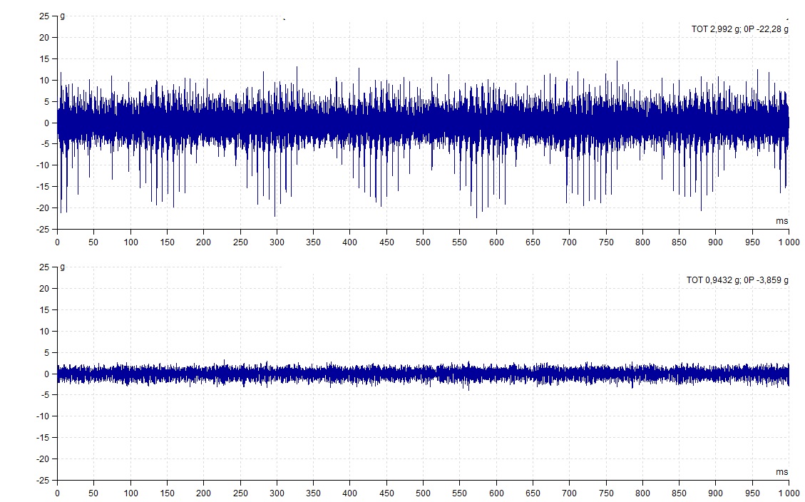
In a time domain plot of acceleration in the range of 500-15000 Hz, we can observe faults in the bearing, which are displayed as regular spikes or impulses.
Real example of time domain plot – damaged bearing:

Comparison of time domain of damaged and new bearing:
