Bearing faults
Bearings are an important component of a machine that supports the rotor system. They are designed to provide low friction on supports and carry the load. Two most common types of bearings used in mechanical equipment are rolling bearings or ball bearings and radial bearings working on the principle of hydrodynamic lubrication. We will focus on the diagnosis of faults in rolling bearings.
Vibration monitoring programs identify bearing faults as one of the most common issues. Less than 10% of bearings run throughout their entire lifespan, 40% fail due to improper lubrication, and 30% fail due to misalignment. Although bearings wear and deteriorate over time, faults are often symptoms of other problems within the machinery or process system. The real problem with bearing elements can be identified as follows:
- Lubrication: Insufficient lubrication.
- Wear, cracks, spalling: Damage to the inner or outer race and damage to the rolling elements. Detecting damaged cages can be challenging with vibration analysis.
- Incorrect assembly:The inner ring is not properly mounted on the shaft or the outer ring is not properly in the bearing housing.
- Excessive clearance: Due to excessive wear or improper selection of bearings.
- Low loadRolling elements skid over the inner ring when they are outside the load zone.
- Loose on shaft: Inner ring loose on shaft.
- Loose in bearing housing: Outer ring loose inside the bearing housing.
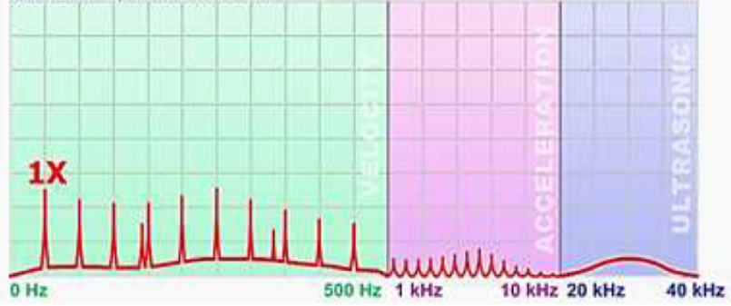
The four rotational frequencies are associated with rolling bearings as shown in the figure below. These fundamental frequencies are FTF (Cage Frequency), Rolling Element Rotation Frequency (BSF), Rolling Element Outer Rotation Frequency (BPFO) and Rolling Element Internal Frequency (BPFI). There are a large number of failure conditions that can be associated with rolling bearings such as bearing wear, lubrication problems, stretched bearing, grooving/EDM, slippage and loosening. These disturbances have a significant effect and the level of effectiveness has been divided into four grades, which will be discussed in the following sections.
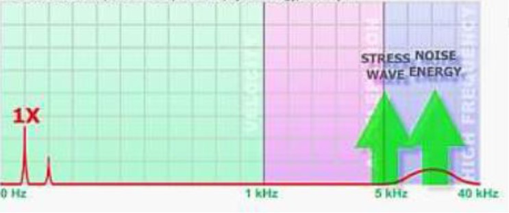
First stage
The earliest signs of bearing problems including poor lubrication appear at ultrasonic frequency (higher than 20 kHz). This is the stage of subsurface damage that causes friction and minor impacts. It has a significant pattern in the frequency range of 5 to 40 kHz. This requires the use of ultrasonic measuring devices. Traditional spectral analysis and time course techniques will not detect an error at this stage. High frequency techniques such as wrapping, demodulation, PeakVue™, Shock Pulse™ and Spike Energy™ can detect the error in the first stage.
Second stage
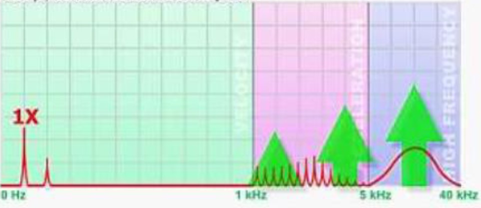
As the bearing fault develops, techniques such as envelope, demodulation and acceleration spectrum are more successful at this stage. The speed spectrum indicator is still ineffective for fault detection at this stage. Small defects in the bearing start to “ring” – they excite the natural frequencies of the bearing components, which are mainly in the range from 500 Hz to 2 kHz. They can also be resonances of the supporting parts of the bearing. At the end of the second phase, sidebands appear around the resonance peaks. This degree can be detected using demodulated high-frequency envelope spectra.
Third phase
As wear increases, in addition to sidebands around these harmonics, bearing defect frequencies and their harmonics also appear. This degree can be determined from the vibration velocity spectra.

Third Stage: Outer Ring:
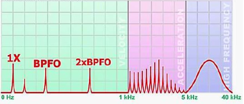
When bearing failure reaches stage three, the damage is more severe and will be visible if the bearing is removed. In addition to time course and high-frequency techniques (demodulation, envelope and acceleration), the velocity spectrum can also be used to detect the fault. If the damage is on the outer track, an impact will occur every time the ball or roller comes into contact with the damaged area and 1XBPFO and its harmonics will appear. The amplitude should be constant, therefore no modulation (or sidebands). If the outer ring rotates, the impact forces will no longer be consistent. When the damaged area passes through the load zone, the shocks will be stronger compared to the shocks when the damaged area is at the top of the bearing where it can be lightly loaded. This increase and decrease in vibrational amplitude generates sidebands in the spectrum. Since the outer track rotates at a rotational speed, the sidebands would be spaced 1X
Third Stage: The Inner Ring
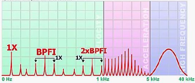
If the damage is on the inner ring, an impact will occur every time the ball or roller comes into contact with the damaged area and 1XBPFI and its harmonics will appear. The amplitude will be highest when the damaged area is in the stress zone, so there will be 1X sidebands.
Third stage: Damage to the rolling element
If the damage is on the balls or rollers, an impact will occur every time the damaged area comes into contact with the inner or outer ring, so the defective ball will appear at 1XBSF and its harmonics. The amplitude will be highest when the damaged element is in the load zone, therefore there will be FTF (cage) sidebands.

Fourth stage
When bearing failure reaches stage four, the bearing is severely damaged and should be replaced. Over time, harmonic frequencies and sidebands may disappear. As the clearance in the bearing increases due to wear, you will see signs of loosening (1X and its harmonics). High frequency techniques become less effective as the condition worsens. The overall levels will increase and the velocity spectrum will clearly show the fault. The spectrum will be very noisy and the noise floor will rise.
Stretched bearing: on the shaft
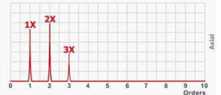
A stretched bearing, which is a kind of misalignment, will generate significant axial vibration. Peaks will often be seen at 1X, 2X and 3X. The bearing can be stretched on the shaft or in the housing. If it is stretched on the shaft, it will “wobble” as it turns, generating rotational vibrations. Since there is very strong axial vibration, it can be confused with fan misalignment and imbalance. The presence of spikes at 2X and 3X would indicate a stretched bearing condition above the imbalance. Relative phase measurement is a key indicator for distinguishing between misalignment and a stretched bearing.
Stretched bearing: in the bearing housing
If the bearing is stretched in the housing, the vibrations will more accurately mimic the misalignment. On either side of the shaft at the face of the part (axial direction) there will be two points where the amplitude will be the highest and the vibration will be 180° out of phase

Inner ring loose on shaft
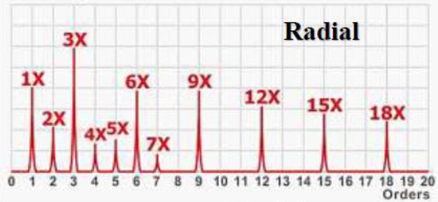
If the bearing is not fitted correctly, the inner ring can slip on the shaft – it does not always rotate at the same speed as the shaft. Depending on the nature of the sliding, the vibration spectrum may be increased by 3X and its harmonics (6X, 9X, etc.). If the sliding motion is intermittent, i.e. it slides a little and then stops, a change in the spectrum may not be observed. If it is constantly sliding, the vibration pattern should change accordingly.
Outer ring loose in bearing housing
If the bearing is not properly installed in the housing, the outer ring may move relative to the housing; it may begin to rotate and even “rattle” inside the cabinet. Peaks at 4X running speed may be increased. The outer ring is visible when moving relative to the house.
